
This run-of-the-river plant is a typical example of late nineteenth-century small-scale (750 kilowatt) low-head hydroelectric power technology. The Fries Manufacturing and Power Company began operating the Idol's Station on April 18, 1898, making it the first commercial hydroelectric plant in North Carolina involving long-distance power transmission, fourteen-miles distance at 10,000 volts. Idol's was an important power source for transportation, lighting, and industry in the Winston-Salem area.
Mechanical

YearAdded:
Image Credit: Courtesy ASMEImage Caption: Idols Station, Fries Manufacturing & Power CompanyEra_date_from: 1898
1984
Society: ASMEMain Category: Electric, MechanicalSub Category: SteamEra: 1890-1899DateCreated: 1891Henry Ford MuseumDearbornState: MIZip: 48124Country: USAWebsite: http://www.asme.org/about-asme/history/landmarks/topics-a-l/electric-power-production-steam/-49-marine-type-triple-expansion--engine-driven-dy, http://files.asme.org/ASMEORG/Communities/History/Landmarks/5537.pdfCreator: Vleck, John Van, Joy, David
This machine, which began operation on December 15, 1891, for the New York Edison Illuminating Company, represents the beginning of large-scale electric power generation in the United States. The generator was designed by chief engineer John Van Vleck, David Joy (known in England for his valve gear), and S. F. Prest.
YearAdded:
Image Credit: Courtesy ASMEImage Caption: Engine-Driven DynamoEra_date_from: 1891
1980

People thought inventor Walter Aiken was crazy when he proposed a railway to the top of Mt. Washington. Aiken built a model of the roadbed and track with a cog rail system, but entrepreneur Sylvester Marsh is credited for launching the Cog Railway and bringing Aiken's ideas to fruition.
In 1858 Marsh applied to the New Hampshire Legislature for a charter to build and operate the steam railway and was granted permission in 1859. Legend has it that an amendment was added offering permission to extend the railway to the moon.
YearAdded:
Image Credit: Courtesy Flickr/Dennis Jarvis (CC BY-SA 2.0)Image Caption: Mount Washington Cog RailwayEra_date_from: 1869
1975
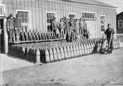
During the 1930's, research into advanced ballistic measurement techniques began at Aberdeen Proving Ground—the world's first large-scale, fully-instrumented ballistic range producing data on the aerodynamic characteristics of missiles in free flight.
YearAdded:
Image Credit: Courtesy U.S. Army RDECOMImage Caption: High Explosive shells at Aberdeen Proving GroundEra_date_from: 1943
1982

This inertia dynamometer is used to test railroad wheels under controlled conditions that can greatly exceed normal service. It is the first and only railroad dynamometer to test track wheels using vertical and lateral loads, as well as thermal braking loads, at the wheel rim. It can also test railway car and locomotive axles.
YearAdded:
Image Caption: AAR Railroad-wheel DynamometerEra_date_from: 1955
1988
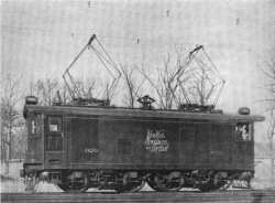
This was a pioneering venture in mainline railroad electrification and was a proving ground for railroad electrification technology. It established single-phase alternating current as a technical and economical alternative to direct current. This concept exerted considerable influence over subsequent systems both in the United States and abroad. The major components of the system were developed by the engineering staffs of the New York, New Haven & Hartford Railroad and the Westinghouse Electric and Manufacturing Company of East Pittsburgh, Pennsylvania.
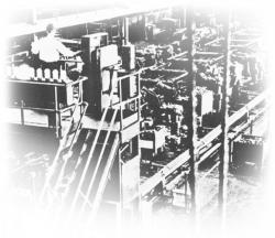
In 1899, during the earliest days of the automobile revolution, A. O. Smith developed a new, lightweight steel car frame. Within a few short years, he was selling these frames to a “who’s who” of car makers including Cadillac, Oldsmobile, and Ford. A. O. Smith’s son, Lloyd Raymond, carried on the family company, expanding the automotive business and introducing the world’s first automated frame production line, the Mechanical Marvel.
YearAdded:
Image Credit: ASMEImage Caption: The entire line at the A. O. Smith Automatic Frame Plant was controlled by the man on the bridge. The long, intricate assembling process completed itself practically without human aid.Era_date_from: 1920
1979

This, the first Curtis vertical turbine built, was constructed by the General Electric Co. for the Newport & Fall River Street Railway Co. It operated in the Newport, R.I., generating station until June 1927. It was transferred to the Harding Street Station of the Indianapolis Power & Light Co. for display and later moved to the company's E.W. Stout Station.
YearAdded:
Image Caption: 5,000-kilowatt Curtis Steam Turbine-GeneratorEra_date_from: 1903
1990
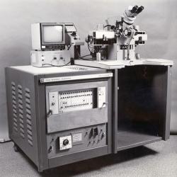
The ABACUS II, designed and built by Texas Instruments, was the first practical automated production machine for the assembly of integrated circuits. Using heat and pressure, it bonded fine gold wire to microscopic contacts on the silicon chip and pin connections on the package.
The ABACUS II could maintain a positioning accuracy of ± 0.00025 inch while bonding up to 375 devices an hour. Following the success of this prototype, almost 1,000 ABACUS II wire bonders were built, making the economical mass production of integrated circuits a reality.
YearAdded:
Image Caption: ABACUS II Integrated-Circuit Wire BonderEra_date_from: 1972
1992
Innovations