
This is one of the earliest uses of engineered water supply and irrigation systems in the United States. The first of eight original acequias was under construction in 1718 and two are still in operation. The remains of one are visible on the grounds of the Alamo. The Acequias of San Antonio are among the earliest engineered water supply and irrigation systems recorded in the United States. The Acequias served an integral role in the growth and stability of the San Antonio community for nearly 200 years.
Civil

YearAdded:
Image Credit: Courtesy: Flickr/Amy the Nurse (CC BY-ND 2.0) Image Caption: The Espada Aqueduct, running over the Piedras CreekEra_date_from: 1718
1968

Maine's heavy snows led turnpike maintenance personnel to bring "left-handed" snow plows into prominence. By using left-handed and traditional right-handed plows in tandem, they were able to distribute snow more evenly - an important advance that has been emulated by many highway maintenance crews across the country.
YearAdded:
Image Credit: Courtesy Flickr/Doug Kerr (CC BY-SA 2.0)Image Caption: Maine TurnpikeEra_date_from: 1947
1999

The Miami Conservancy District flood control project was the direct result of the disastrous flood of 1913, when waters from the Miami, Stillwater, and Mad rivers flooded Dayton and surrounding communities in the Miami Valley. More than 400 lives were lost and property damage exceeded $100 million. When Dayton flooded, great fires raged, adding to the devastation. Many believed that the area would never recover.
YearAdded:
Image Credit: Courtesy Flickr/bobosh_t (CC BY-SA 2.0)Image Caption: The Taylorsville Dam, one of the five dry damns to come out of the Miami Conservancy DistrictEra_date_from: 19221972
- Concrete Conduit
- Dry Dam
- Earth-Core
- Flood Control
- Flood Prevention Committee
- Great Depression
- Levee
- Mad River
- Miami Conservancy District
- Miami River
- Retardation Basin
- Stillwater River
- 1920-1929
- 1922
- 1972
- 45424
- ASCE
- Civil
- Flood Prevention Committee
- Great Dayton Flood
- Morgan, Arthur Ernest
- OH
- USA
- Water Supply & Control

The 1.6-mile Holland Tunnel was the first underwater vehicular crossing of the Hudson River and the first tunnel specifically designed for automobiles and trucks. It dramatically reduced the time required to traverse the Hudson River, a trip previously possible only by ferry.
A major difficulty when tunneling beneath a river is to keep water and mud from inundating the workers and equipment in the tunnel. Builders of the Holland Tunnel used a shield that enveloped the work site as the excavation progressed; this also avoided obstruction of shipping traffic during construction.
YearAdded:
Image Credit: Courtesy Flickr/Chris Leung (CC BY-SA 2.0)Image Caption: Holland TunnelEra_date_from: 1927
1982

Spearheaded by Hugh Cooper, the Keokuk Dam & Power Plant served as a prototype for many future power plants. The project harnessed the hydropower of the Mississippi River, between Keokuk, Iowa and Hamilton, Illinois.
The crest of the dam is nearly a mile long. The dam structure features 119 arch spans between six-foot-thick piers and a 110-foot-wide pneumatic lock. Combined with the lock, the dam reduced travel time for steamboats by nearly two hours.
YearAdded:
Image Credit: Courtesy Flickr/Michael R. Allen (CC BY 2.0)Image Caption: Mississippi River Lock and Dam number 19Era_date_from: 1913
1988
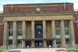
The North Island Main Trunk Railway permitted overland travel and development of the New Zealand hinterland. Built under challenging conditions and over difficult terrain, all cuts, fills, and tunneling were minimized by careful use of the topography and by innovative engineering.
Over 30 miles south of Taumarunui, the North Island Main Trunk Railway climbs 2,086 feet to the edge of the great Waimarino Plateau. But over the last seven miles, an abrupt increase in altitude of over 700 feet posed an engineering challenge that led to the design of the famed Raurimu Spiral.
YearAdded:
Image Credit: Courtesy Flickr/SibleyHunter (CC BY 2.0)Image Caption: Wellington Railway Station, part of the original North Island Main Trunk RailwayEra_date_from: 1908
1997

In the mid-1800s Virginia City was America's greatest producer of high-grade silver and gold ore. When mining activities began, natural springs provided water to the camps. As the population grew, the Virginia and Gold Hill Water Company was formed to address the need for more water. The company first drew water from tunnels that had been driven into the mountains by prospectors. Water was stored in wooden tanks and sent through pipes into the town.
YearAdded:
Image Credit: Courtesy Flickr/Jeff Moser (CC BY-ND 2.0)Image Caption: Marlette Lake Water SystemEra_date_from: 1873
1975

Most of the locks were 184 feet long and 36 feet wide, able to handle boats up to 160 feet long. The sandstone locks (along with wood miter gates, rock-filled timber-crib dams and bypass canals with guard gates) created a slackwater navigation system stretching over 90 miles.
YearAdded:
Image Credit: Courtesy Flickr/gb_packards (CC BY-ND 2.0)Image Caption: Muskingum River LockEra_date_from: 1837
2000

In the 18th century, French architect Claude-Nichols Ledoux was known for forging architectural beauty with industrial efficiency. One hundred years later his vision was given new life through the design of the Louisville Water Company Pumping Station.
YearAdded:
Image Credit: Public Domain (Author's Choice)Image Caption: Louisville Water WorksEra_date_from: 1830
1981

In the early 1830s, the merchants of Bristol, long dissatisfied with their communication with London, began to wonder if the new railroad technology might be a solution to their problem. The Bristol Chamber of Commerce, the Merchant Adventurers and other local industrial bodies formed a committee in 1833 to discuss the ambitious proposal of laying a railway to London. Matters progressed swiftly. Money was advanced and the search for a first-class engineer to guide the effort.
YearAdded:
Image Credit: Courtesy Flickr/Ingy The Wingy (CC BY-ND 2.0)Image Caption: Great Western Railway lower quadrant semaphore signals; 1952Era_date_from: 1838
2005
Innovations